Week 10: Final Project

 
IMG_3494.jpg

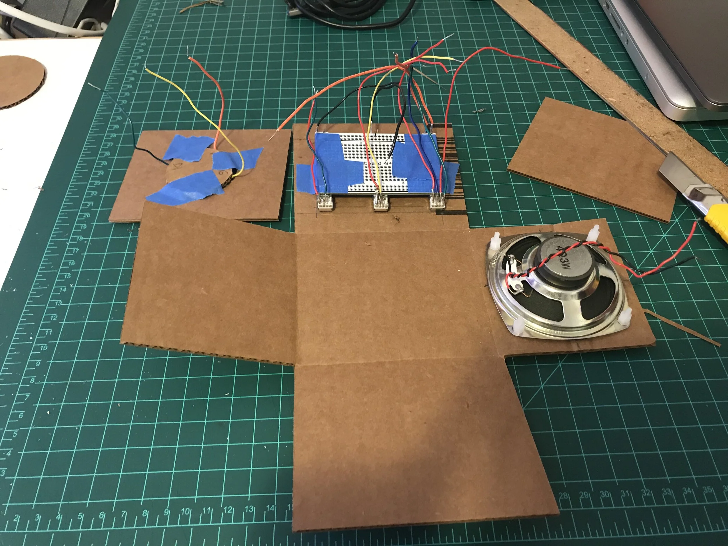
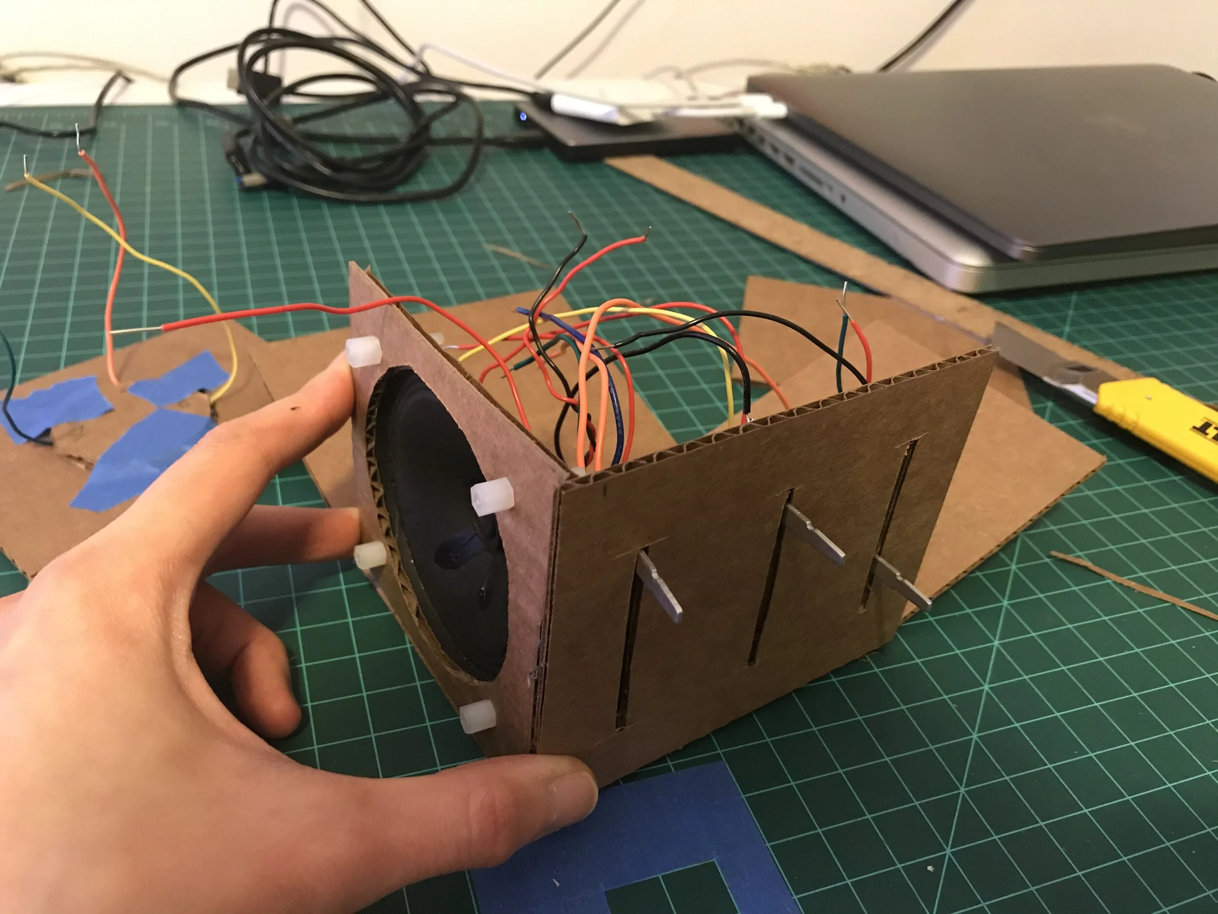
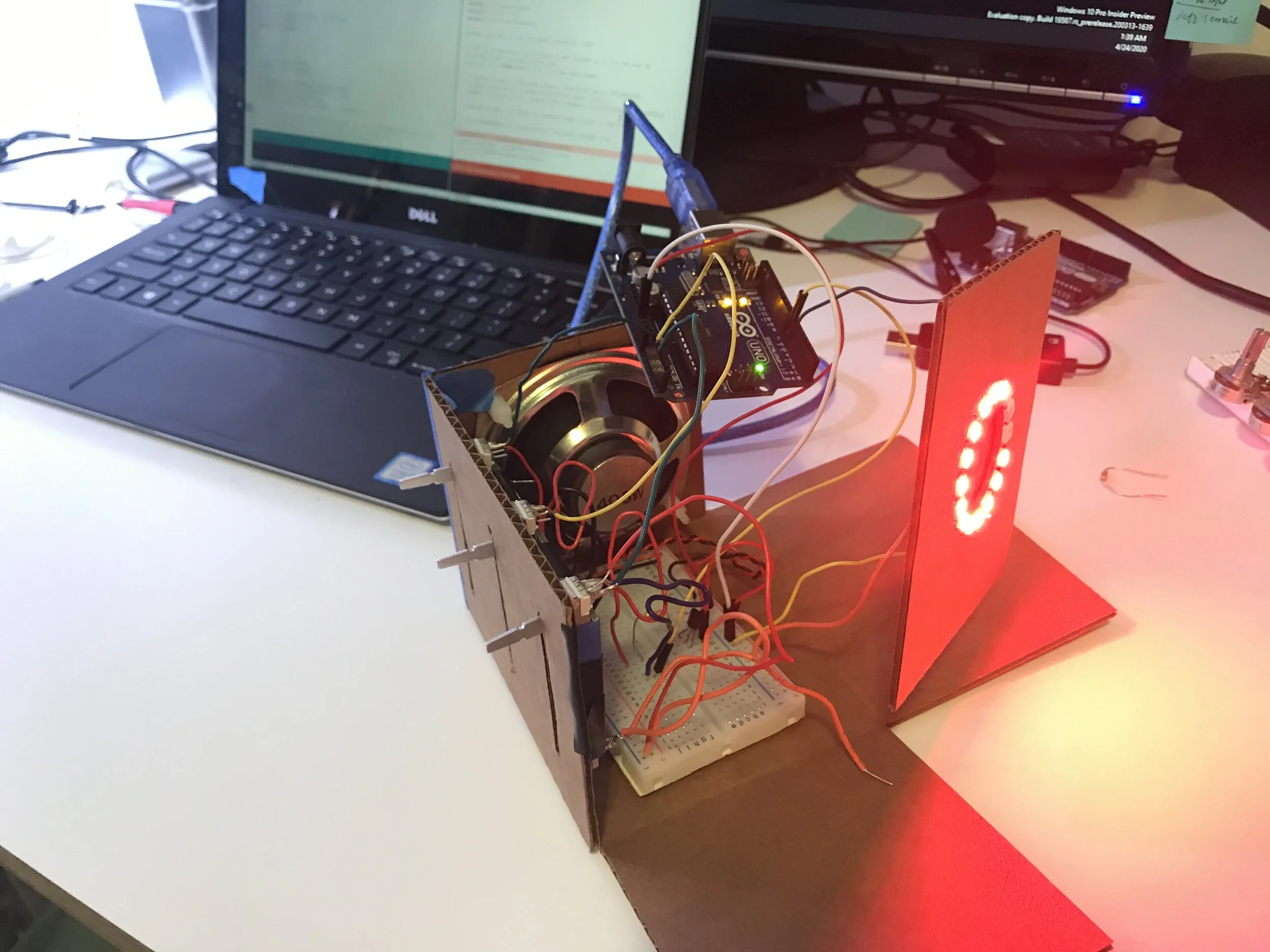
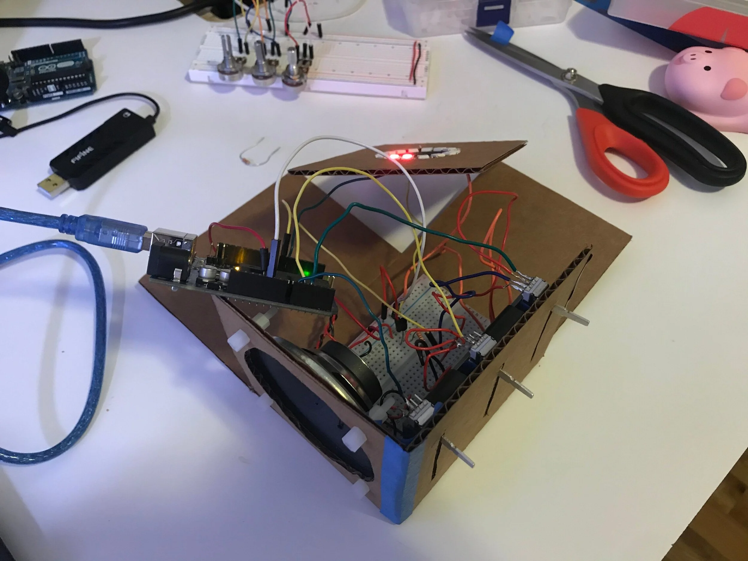
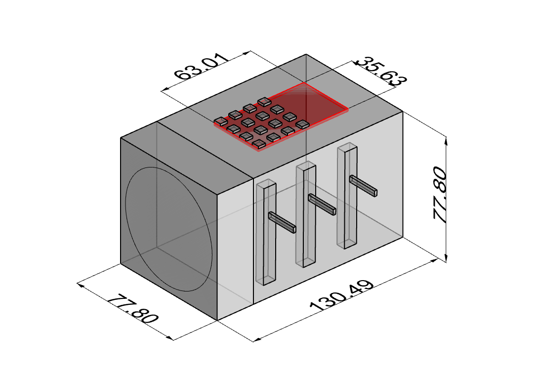
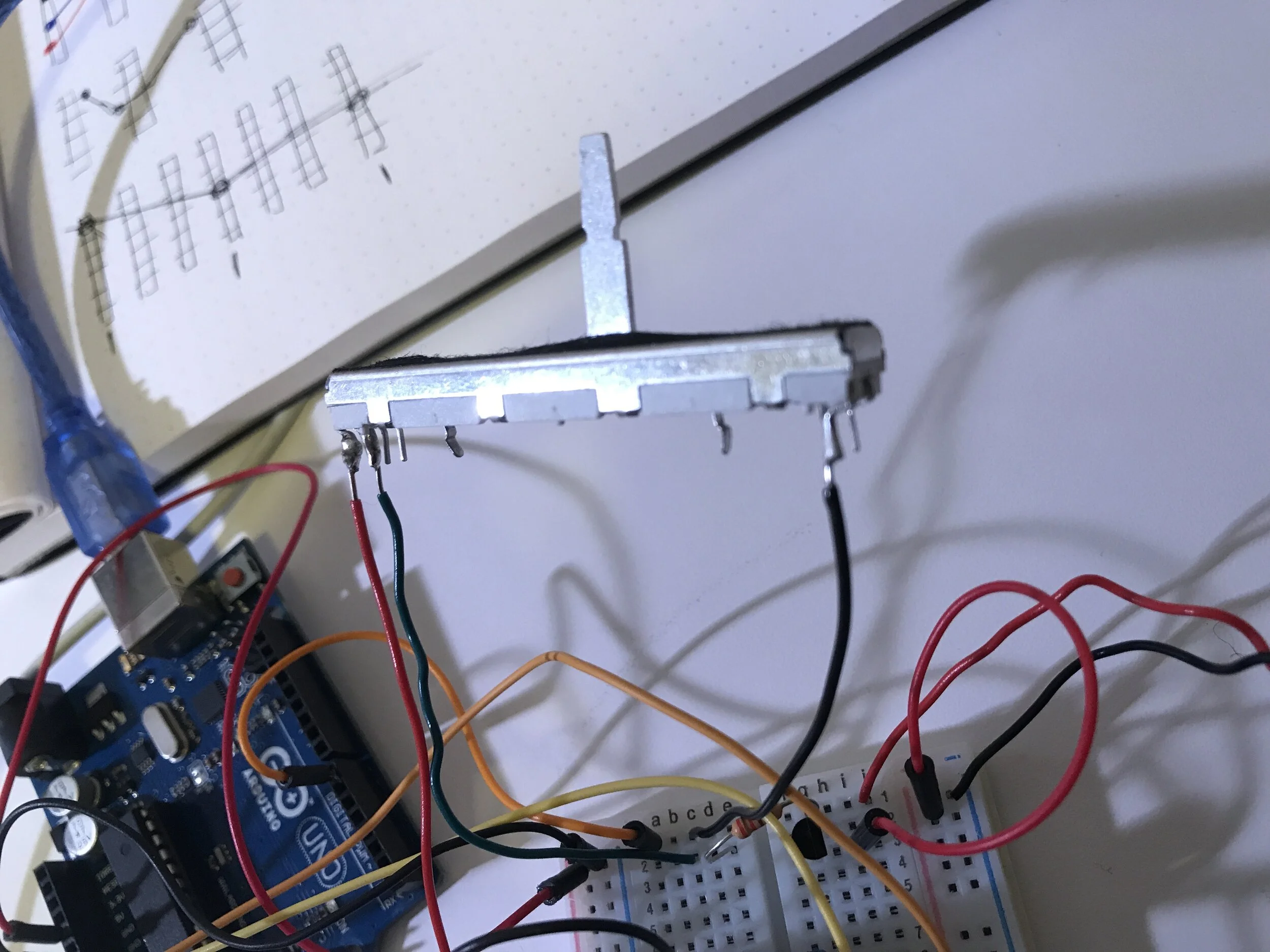
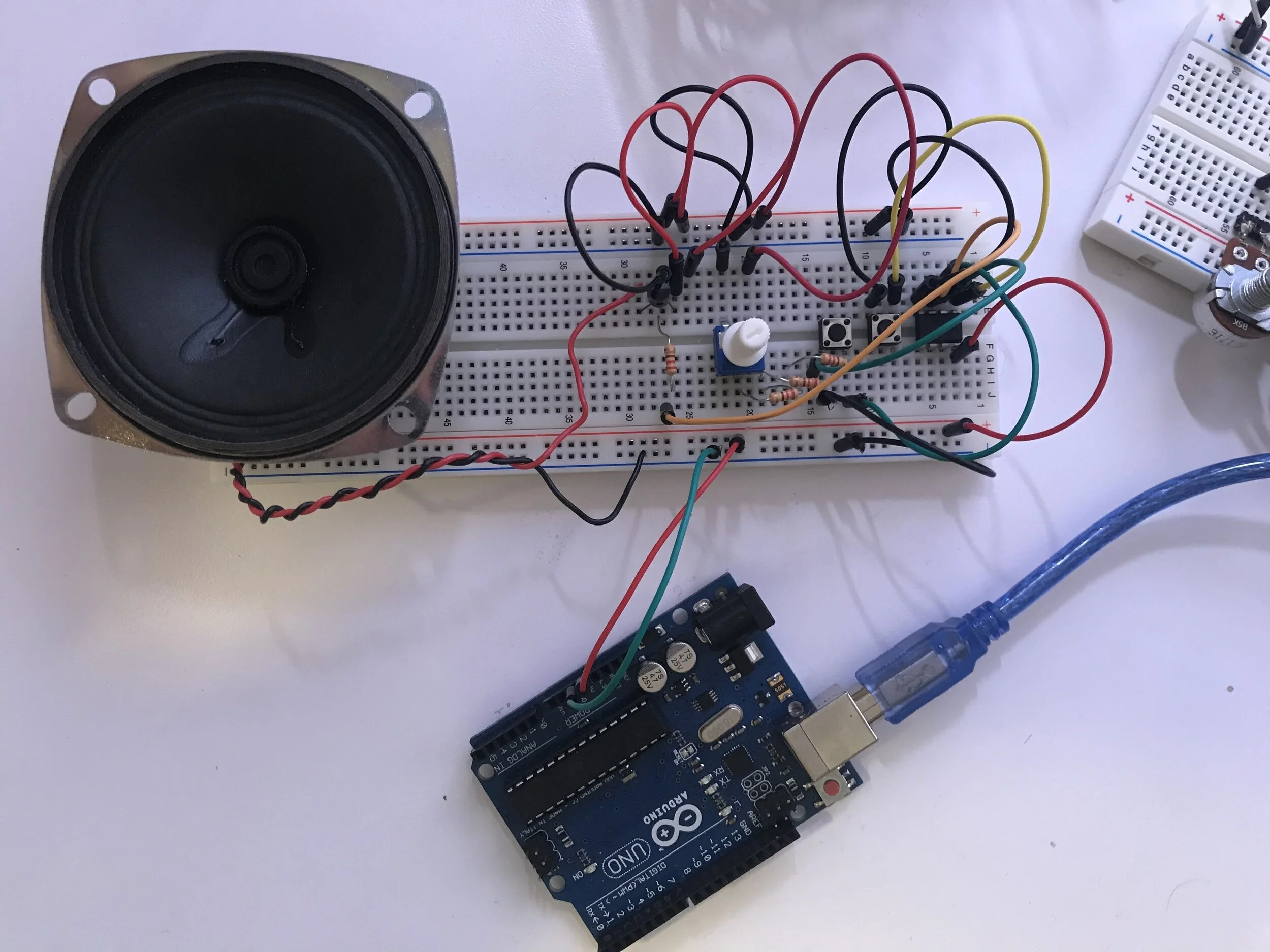
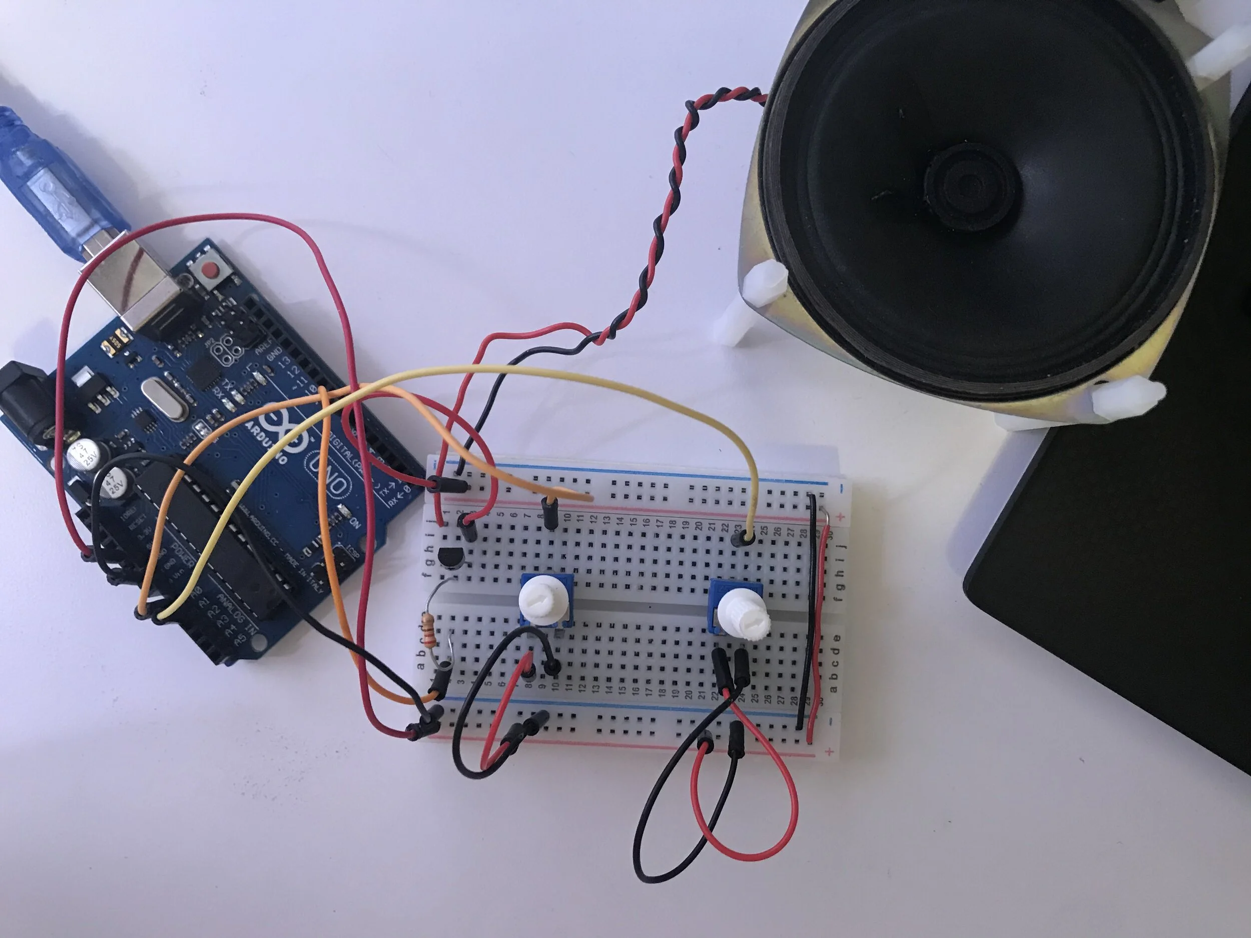
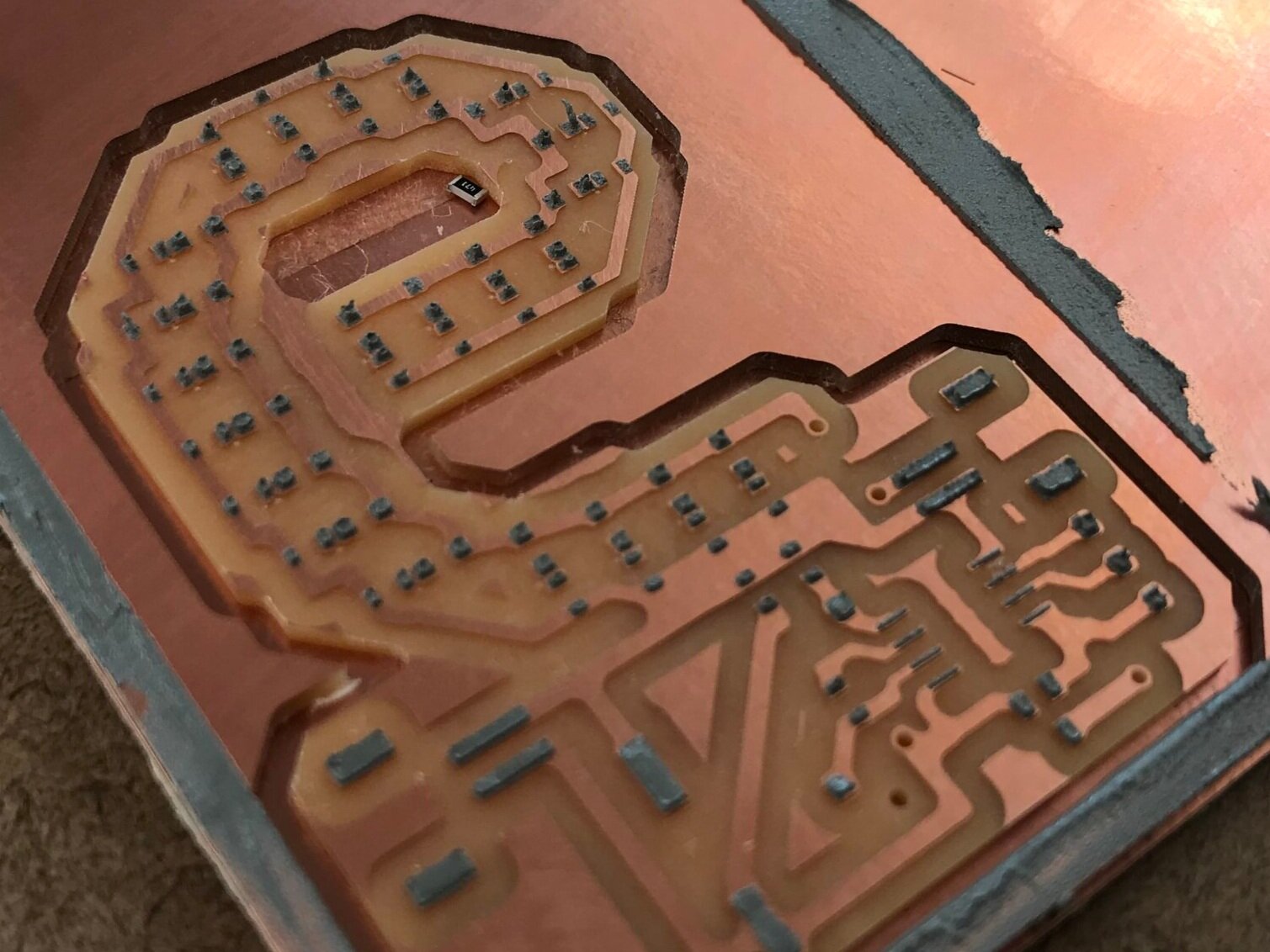
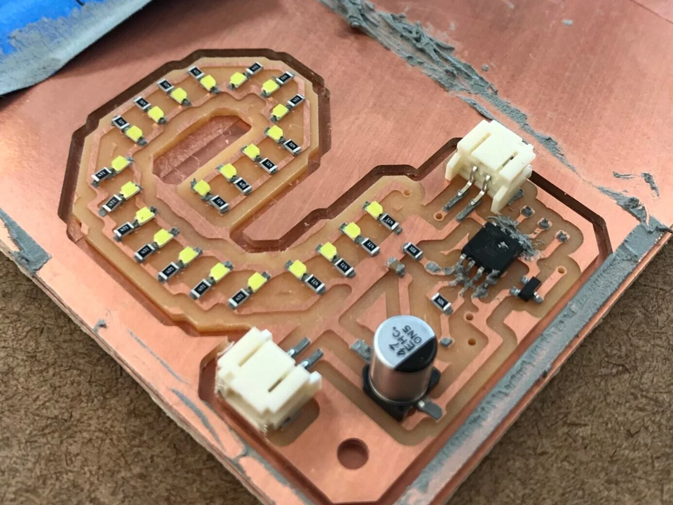
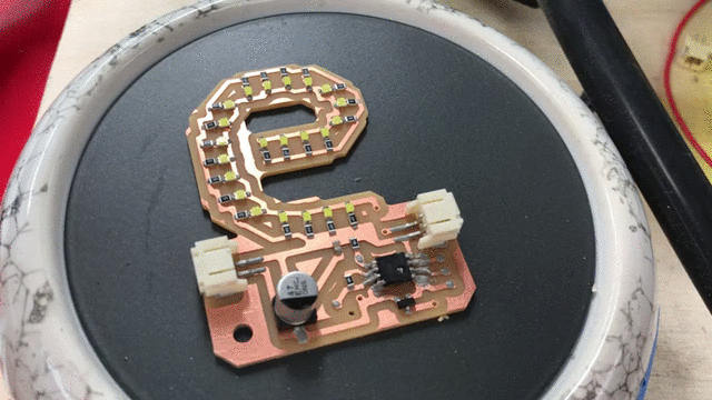
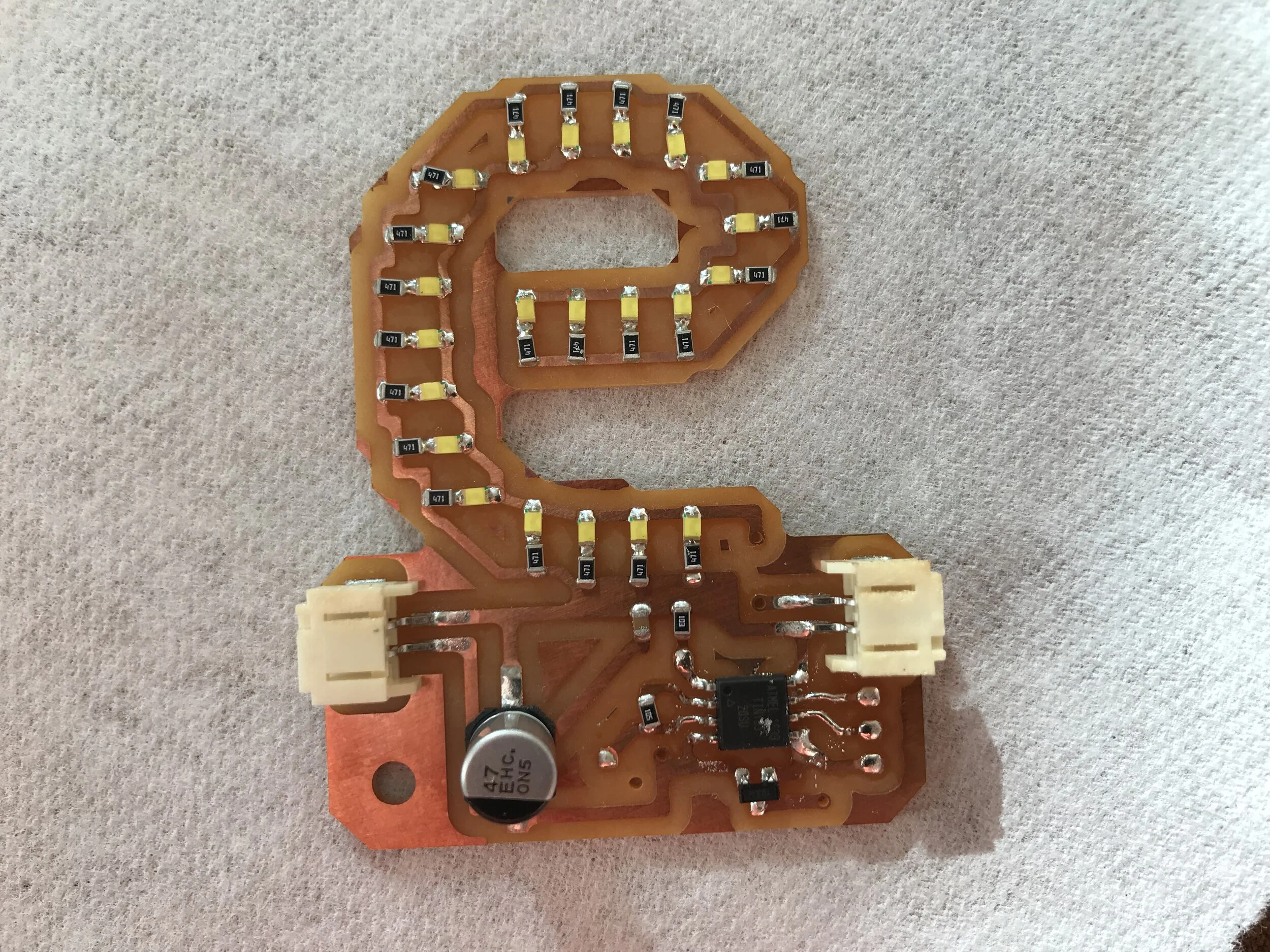
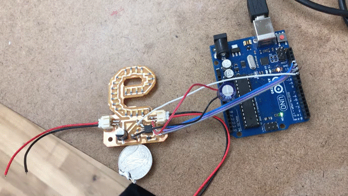
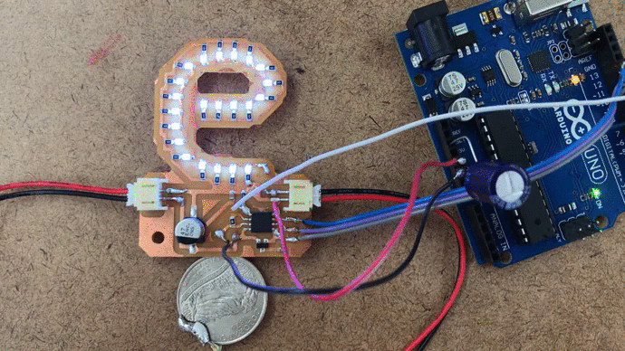
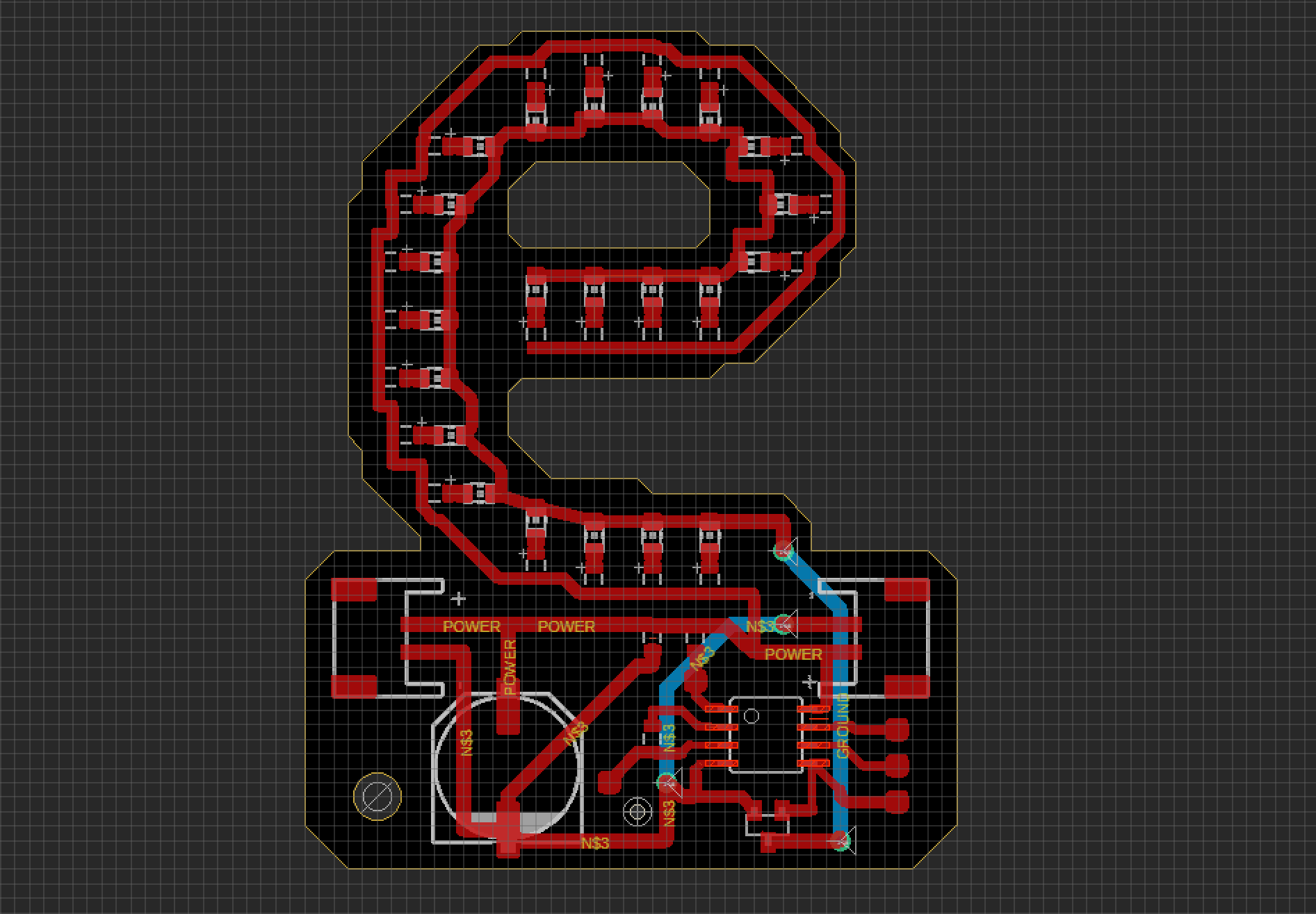
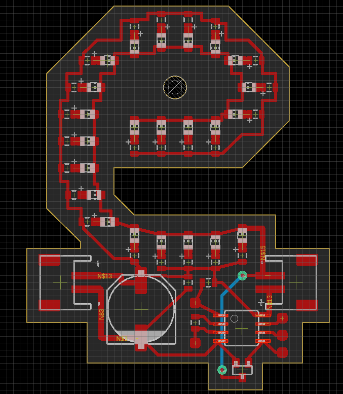
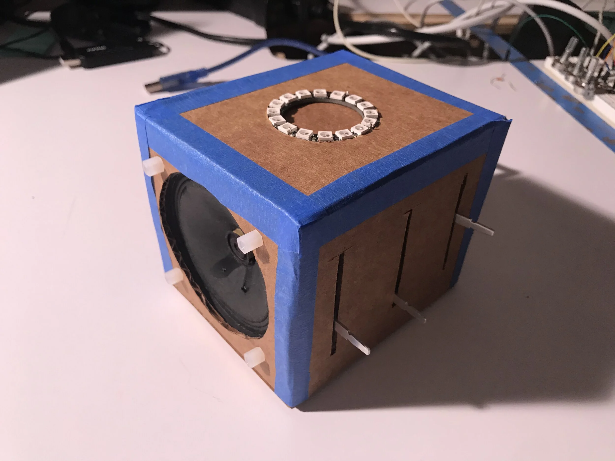
This is my musical light box prototype. I got the hardware parts and configuration to work the way I had envisioned without the PCB and surface mount components of course. For the fabrication I was hoping to use a laser cutter and a more sturdy material but given the remote learning situation I had to resort to cardboard and a knife. I’m also missing slider knobs.

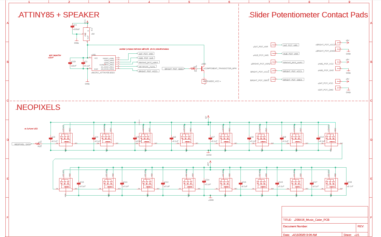
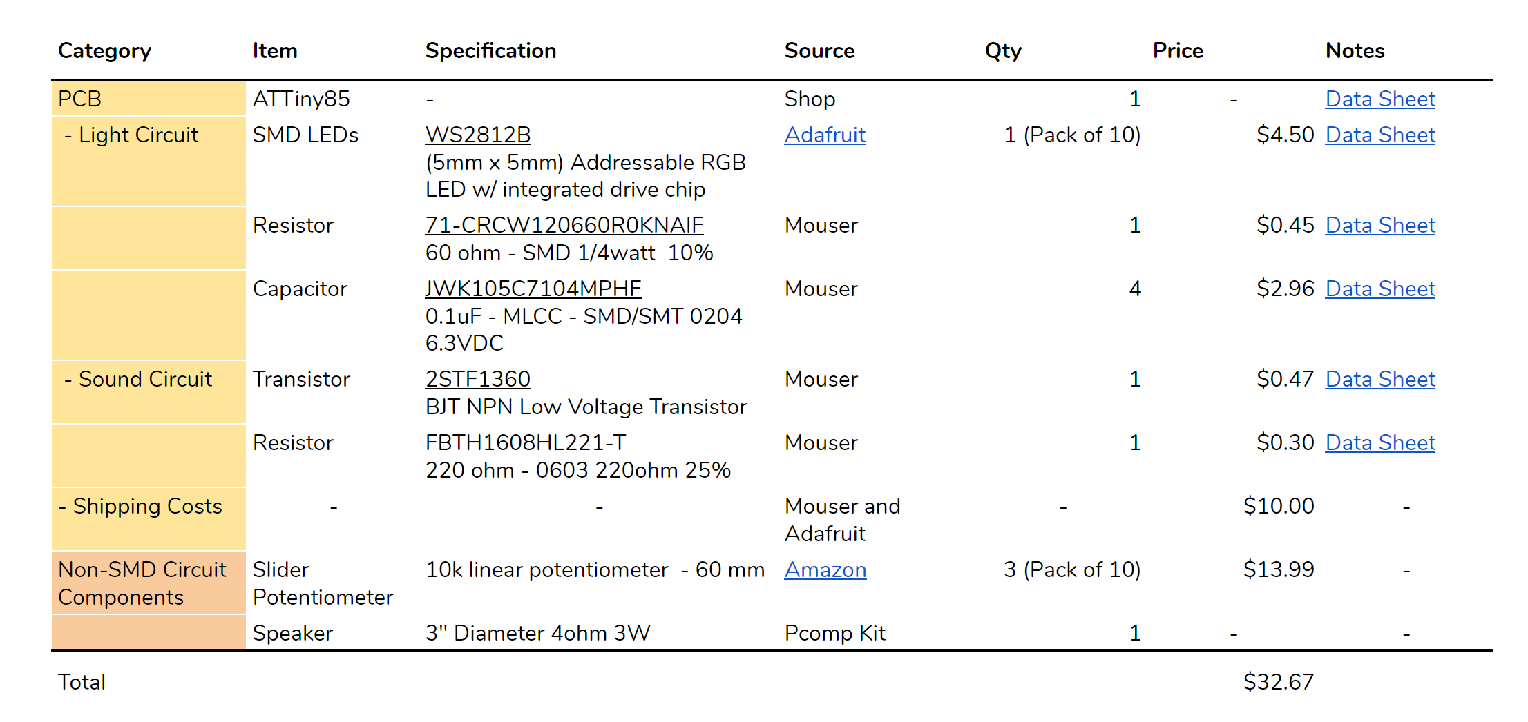
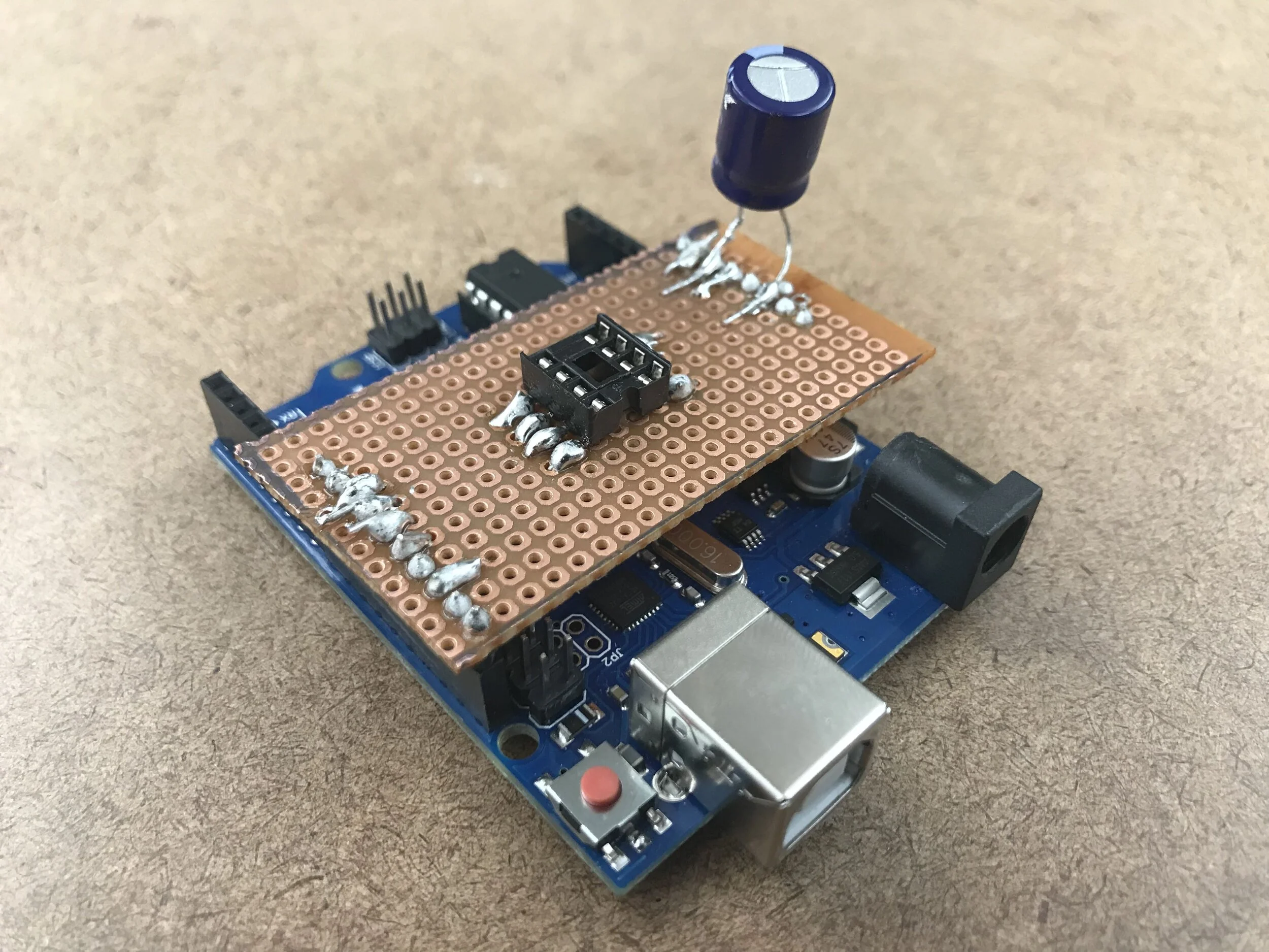
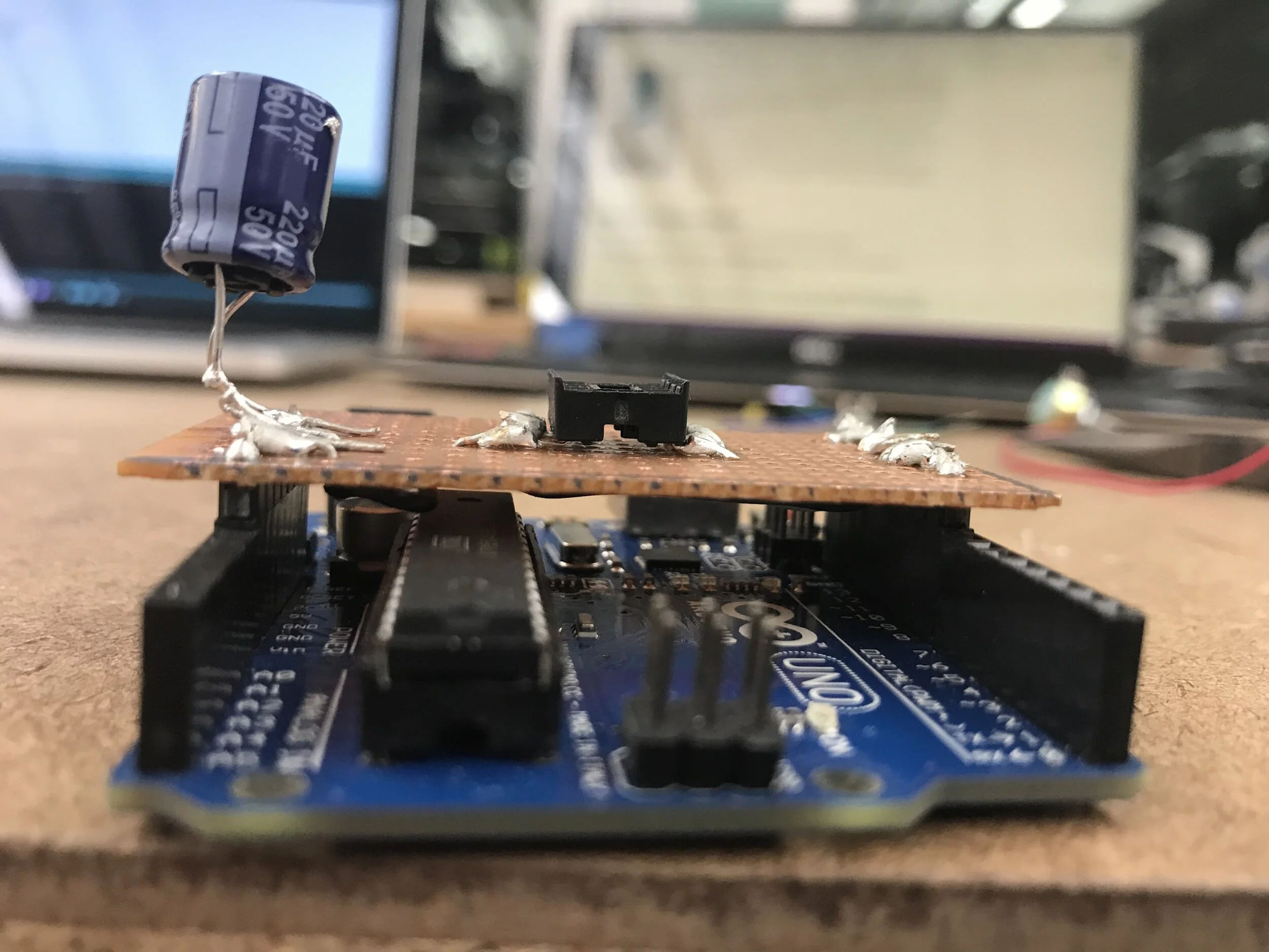
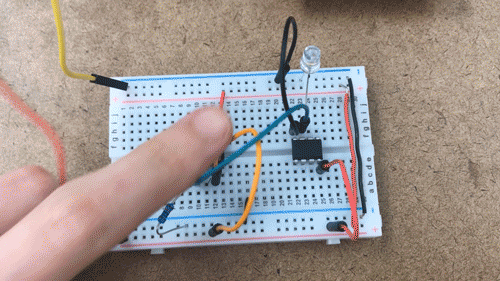
The prototype hardware:

  • Arduino Uno

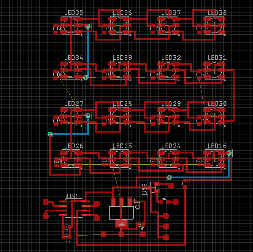
  • Neopixel 16 LED Flora Ring

  • 4ohm 3W speaker

  • 3x 10k Slider Potentiometers

  • BJT NPN Resistor

  • 100ohm resistor

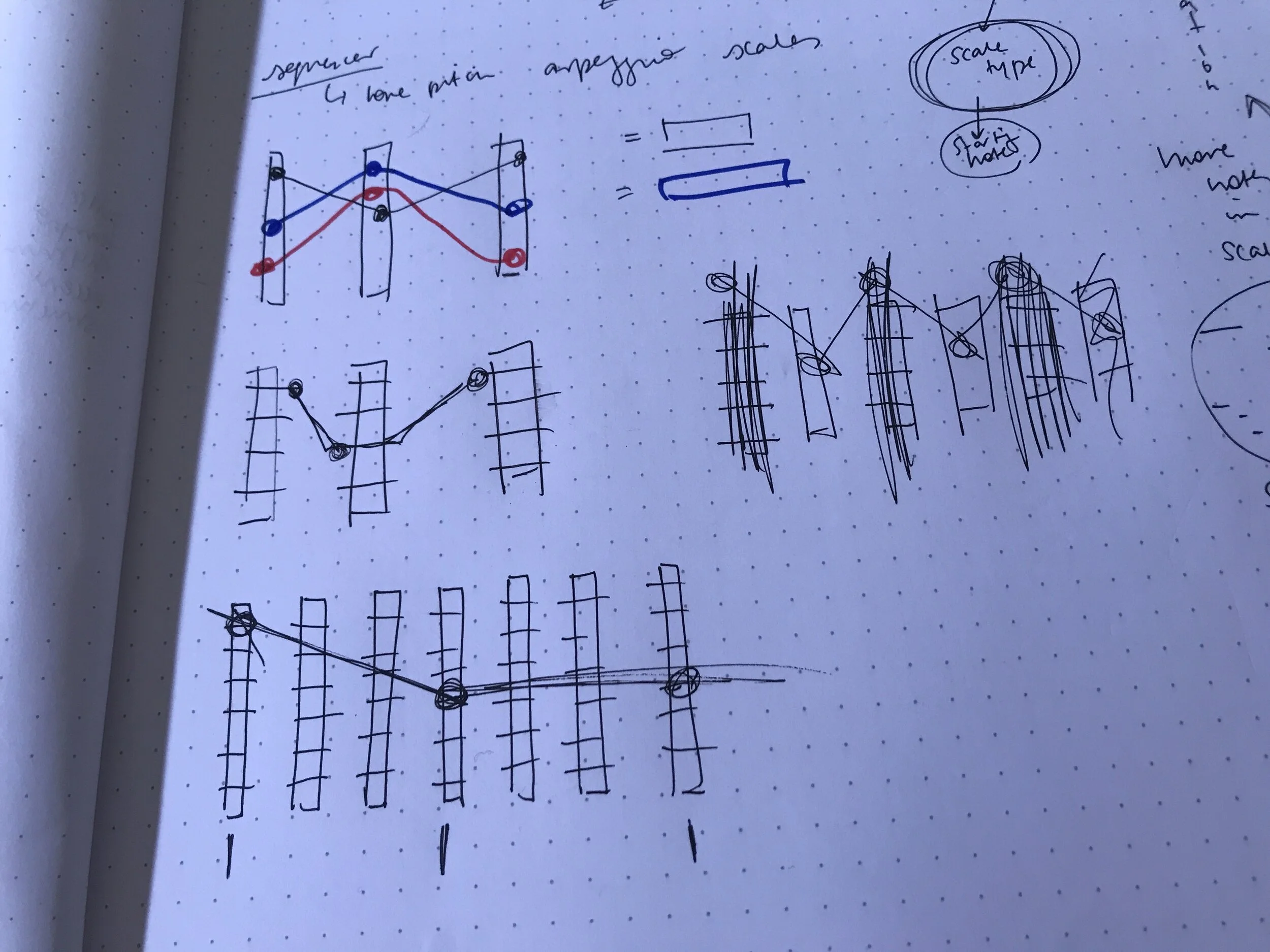
For the musical mapping (which is all on the coding side) it is still in the preliminary stage where a single tone is generated from the changing sliders instead of a melody. I plan to continue working on that and add the feature.


process images


PCB Eagle Files


schematic

Week 9: Eagle PCB Design


The latest version of my Eagle schematic and board file. I am planning to make a ground plane so there are no ground routes. Question, do I still need to connect all the ground plane “islands” together? Currently, I’m stuck trying to trouble shoot routing the capacitors. They seem to be all connected in parallel in the schematic and yet some of them refuse to connect with the power and ground pins on the LEDs. The link to the eagle files.

Schematic2.PNG
board_screencap2.PNG
Box.PNG

This is my quick prototype of the music box with measurements in mm, this is the minimum volume that the box needs to fit the components. I will resize it bigger for the next iteration but this model helps me get a sense of the size that I will be working with. The red is the PCB, approximately it can be about 65mm x 35mm but potentially bigger. The speaker is going to be the component that takes up the most space.

Week 8: Prototype continued

I did some thinking on how to combine the sound and color control together. I was inspired by this online arpeggio generator on the Chrome Music Labs site. This generator demonstrates not just what different scales sound like, of course, but how rich the musical texture can get by playing multiple notes within the same scale rapidly. From this, I came up with this mapping for the HSB values: hue - notes for the scale (C, D, E, F, G, A & B); saturation - duration of notes and length of notes; brightness - audio gain.

I am still sticking with 8-bit audio so it won’t sound as elegant as the Chrome Lab example but given the current situation, I think it’s best to just continue with what components I have. For the mapping to work, it will be a lot of list manipulation and picking pitches from this note table written by Brett Hagman.

HSB mapping

saturation explained further

 
IMG_3453.JPG

As for the circuit, it took me a minute to figure out the wiring for the 10k slider potentiometers I got. But I figured out that since it’s double linear, there are 2 sets of 3 pins that are typical in regular pots. I’m still not sure which one is the variable pin though. Still figuring that out. I know VCC and G are on either end but I’m not sure which is the variable since the resistance readings from my multimeter are the same regardless of which two pins on either side the pens come in contact with.


To keep as future reference:

Initially, I had a different idea of mapping the three potentiometers. Whatever position the pots are at, the interpolation of the points will determine where the notes in the rest of the scale is. The three would just be the beginning, middle and end points of the scale. The rest would be up to where the lines drawn would cross.

IMG_3454.JPG

Week 7: Protoype

For the prototype I split up the two features: the sound and the color output. I separated the two for now because I am still working on the mapping the correlation of color parameters and sound. For the color prototype I am using a neopixel ring that is changing in Hue, Saturation and Brightness values from 3 potentiometers mapped to each parameter. For the sound part, I am for now sticking to what the arduino and ATTiny is capable with producing sound, 8-bit tones. The pitch and duration of the notes are controlled with two separate potentiometers. For the future iteration I will look into filter ICs and develop the arduino code so that it can play more complex melodies instead of just the one pitch that is controlled by the changing potentiometer values.

hsv_colorWheel.gif

Initially, I was following a step-sequencer instructable that uses an ATTiny to get a sense of what is possible with a small chip. I did not manage to get it to work as intended but learned a few things along the way while troubleshooting the issues I was running into.

Things I learned and figured out:

  • The speaker (4ohm 3W) I was using did not sound loud enough. I knew I needed a transistor but I had to do some research to figure out what kind actually works for this application. After some digging I learned that BJT NPN types can amplify audio because the current from the Base will act as a multiplier as it joins the current from the Collector.

  • The author for the instructable was reading both a switch and a potentiometer from a single pin on the ATTiny because they ran out of pins on this very limited chip. The pin would be reading analog values and since potentiometers have a minimum resistance, if the analog value fell below that minimum resistance then logically the switch (connected to ground and the internal resistor set to pull up) would be on.


Next Steps:

  • Design the musical correlation between sound and color

  • Look into other ways I can manipulate the sound using perhaps filter ICs

  • Try to combine the two parts together onto one ATTiny

Step - sequencer board

Step - sequencer board

Simplified “instrument” board

Simplified “instrument” board


Bill of Materials - link to spreadsheet

BOM.PNG

Week 6: Final Project Proposal


My idea is a simple synth box that outputs music based on HSB color controls. The user can only control Hue Saturation Brightness values to change the musical output of the device.

There will be three slider potentiometers to control the three parameters, an LED neopixel ring to show the user what color they’re at, a power switch and speakers to output the music in correlation with the color (maybe an audio jack as well).

One area in the concept that needs more development would be determining how the sound correlates to the changing values. The questions to ask are: “what does the red hue sound like?” , “what does low saturation sound like?, etc…

I’m inspired by this nifty device created by this duo based in China, FM3. They created the Buddha Machine which outputs cyclical ambient music and you’re limited to only a few controls like the track number, the volume and the power dials. It was a really successful device and I think it’s mainly due to its simplicity.

71AVYOKEINL._SS500_.jpg
buddhaglass.jpg

Week 2 : Introduction to ATtiny85

attiny1.gif

This was my first time learning about the ATtiny85. I had no idea that I can this chip to replace arduinos for simple I/O tasks.. This is going to be great for future projects, where I can first prototype with an arduino then replace it with an ATtiny with the same code so I can get my arduino back for future projects.

To summarize the process of bootloading the ATtiny85:
1. the arduino uno is set up as an ISP (In System Programmer) by uploading the ‘Arduino as ISP’ example code
2. the arduino is wired to the chip
3. in the IDE, the programmer is set to ‘Arduino as ISP’, the ATtiny85 is selected as the target board with the correct clock setting and then the bootloader is burned
4. once successfully burned, you can upload the code but through the “upload using programmer”option

To make it more efficient with the wiring of the ATtiny to the arduino, we made a programming jig that would sit perfectly on the board.

For the input/output assignment, I uploaded some code that would turn an LED on with the push of a button. I had to keep it simple for the sake of time because I spent a lot of time this week trying to figure out the problems I was running into with uploading the bootloader from my PC, which I still have yet to figure out (I ended up using a production macbook).