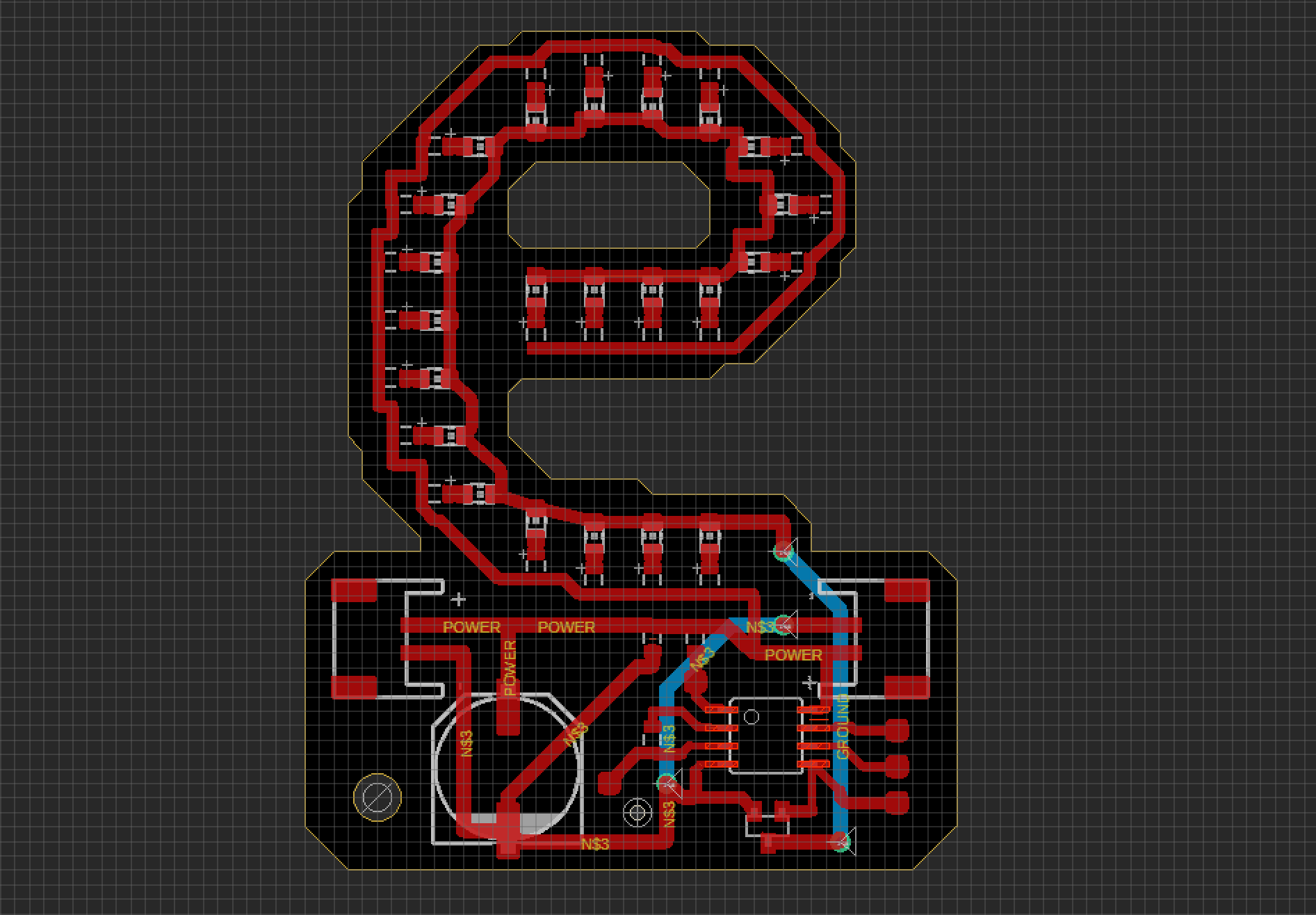
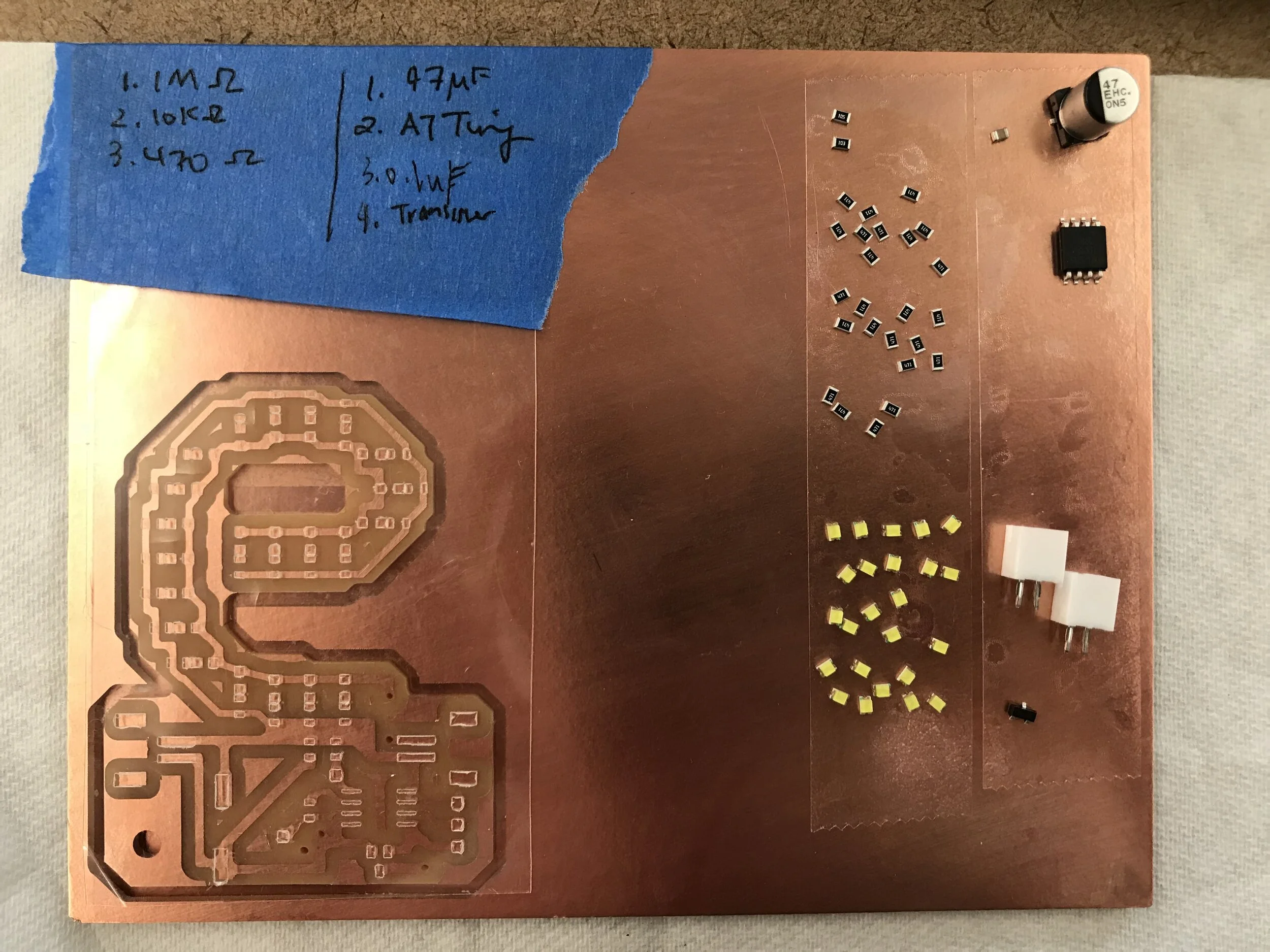
I got assigned the letter ‘e’ in the ‘I dislike pigeon’ marquee sign. A PCB (comprised of 22 surface mount LEDs and other components) was created to make this capacitive touch light-up board. The process is documented down below:
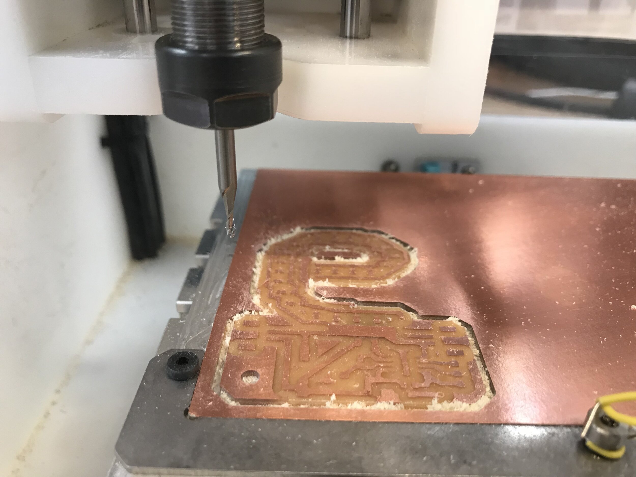
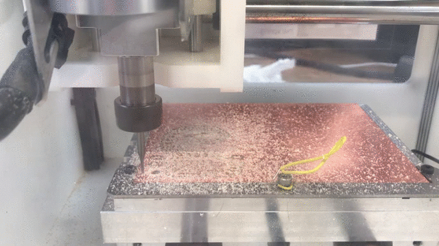
milling
Using the Other Mill PRO and the Bantam Tools routing app, the PCB was milled out from a single sided copper board. The design was developed in the previous week with the Eagle software. 3 bits were used: 1/16” End Mill, 1/32” End Mill and the 0.003” 30 degree engraving bit.
soldering
After milling the copper plate, I also milled out the ‘cream’ layer for the solder paste on a sheet of thin transparency which would be used as a stencil. This really saved me time and stress of having to manually apply solder paste on each connection point with a pin. After aligning the transparency to the plate, the paste was swiped across like you would for screen printing. Then the components were place accordingly.
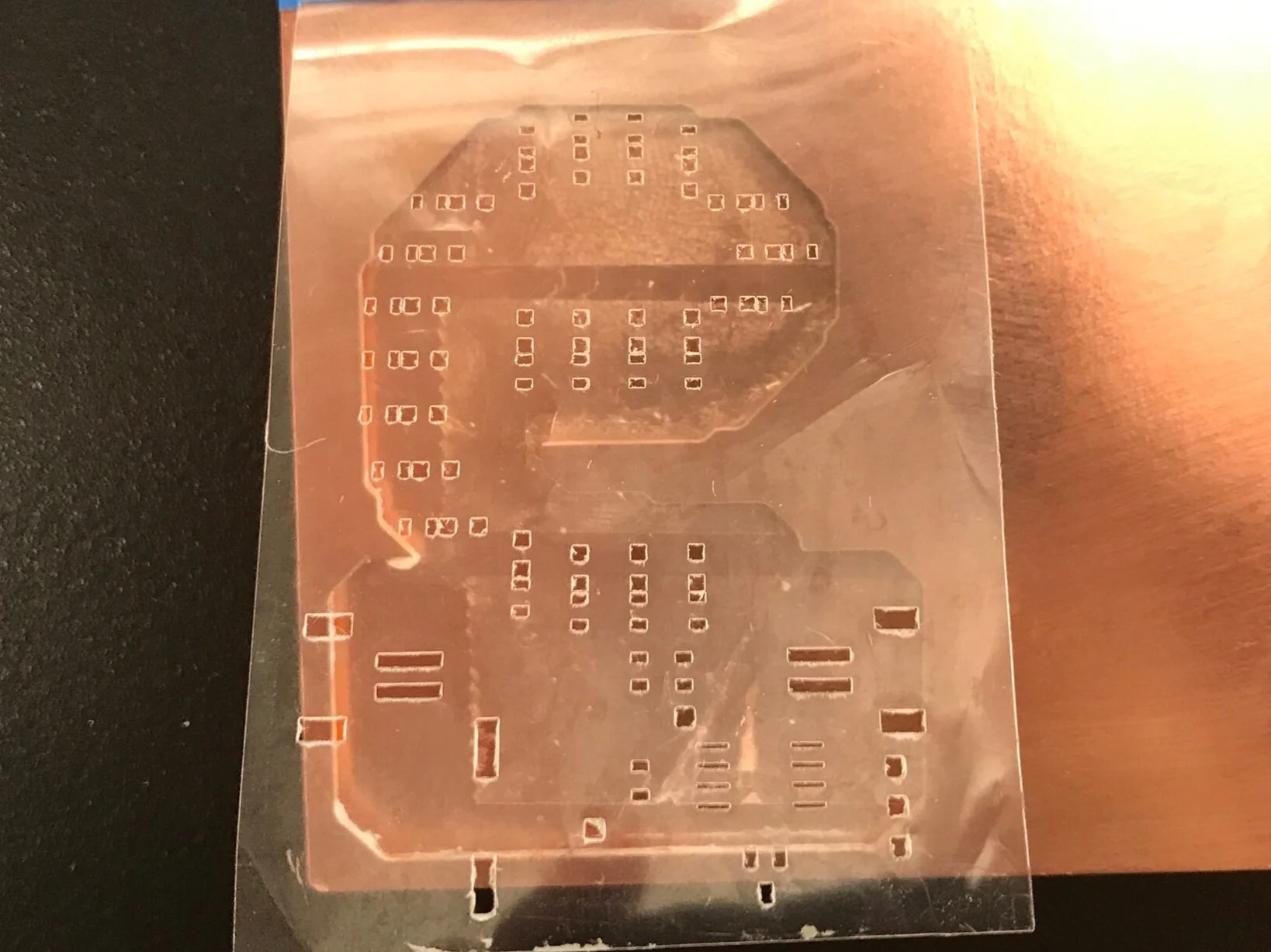
cream layer milled out on transparency
the assembly board with the PCB, the stencil and components
solder paste in place after swiping the paste over a stencil
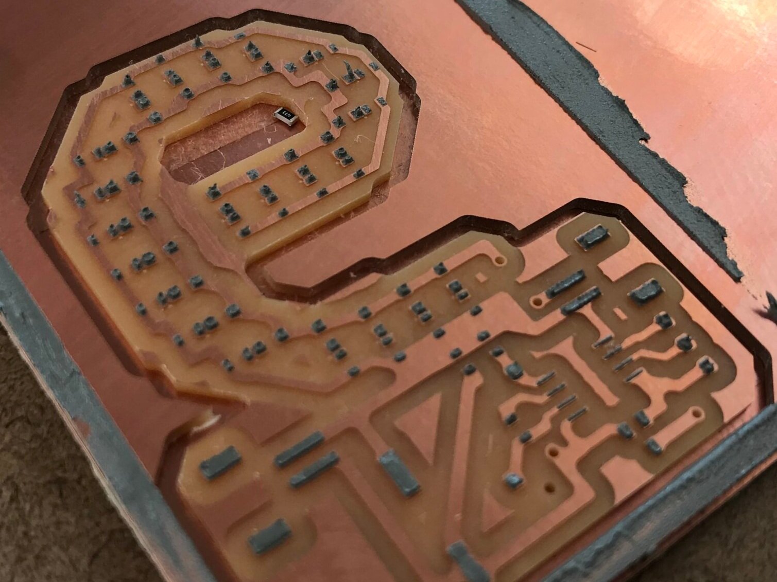
all the components in place ready for the heat gun
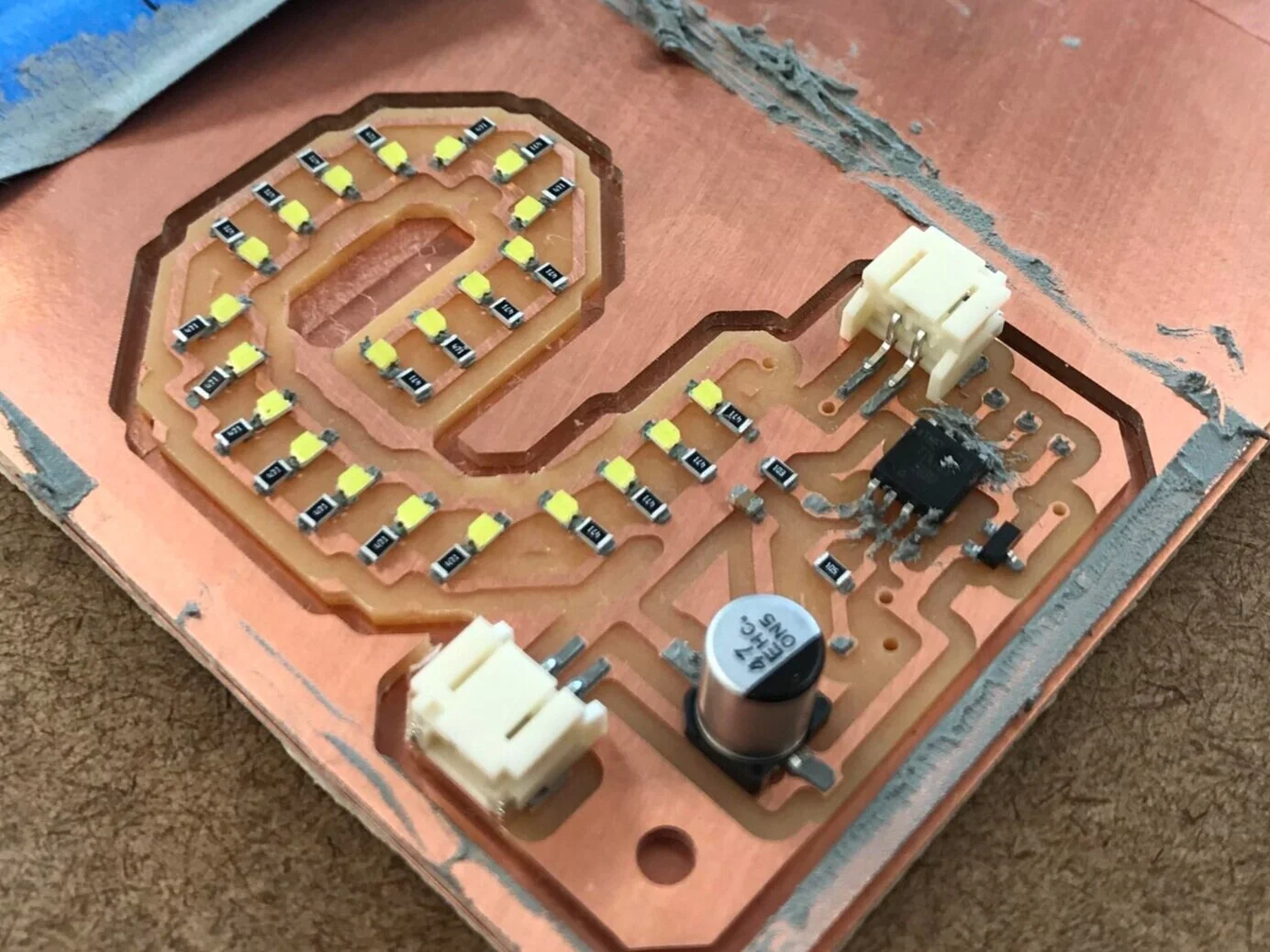
Once all the components were placed, the PCB was placed on a coffee mug heater and the heat gun applied from above. After a few seconds the solder paste heated up and formed a bond with its connections. Some of the components had not properly been soldered so I had to manually re-solder with the iron. After all the components were in place, I soldered the air-wires, programming wires for the ATTiny and the capacitive sensor which in my case is a quarter.
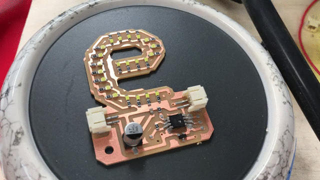
the PCB on the heating plate and heat gun applied over it
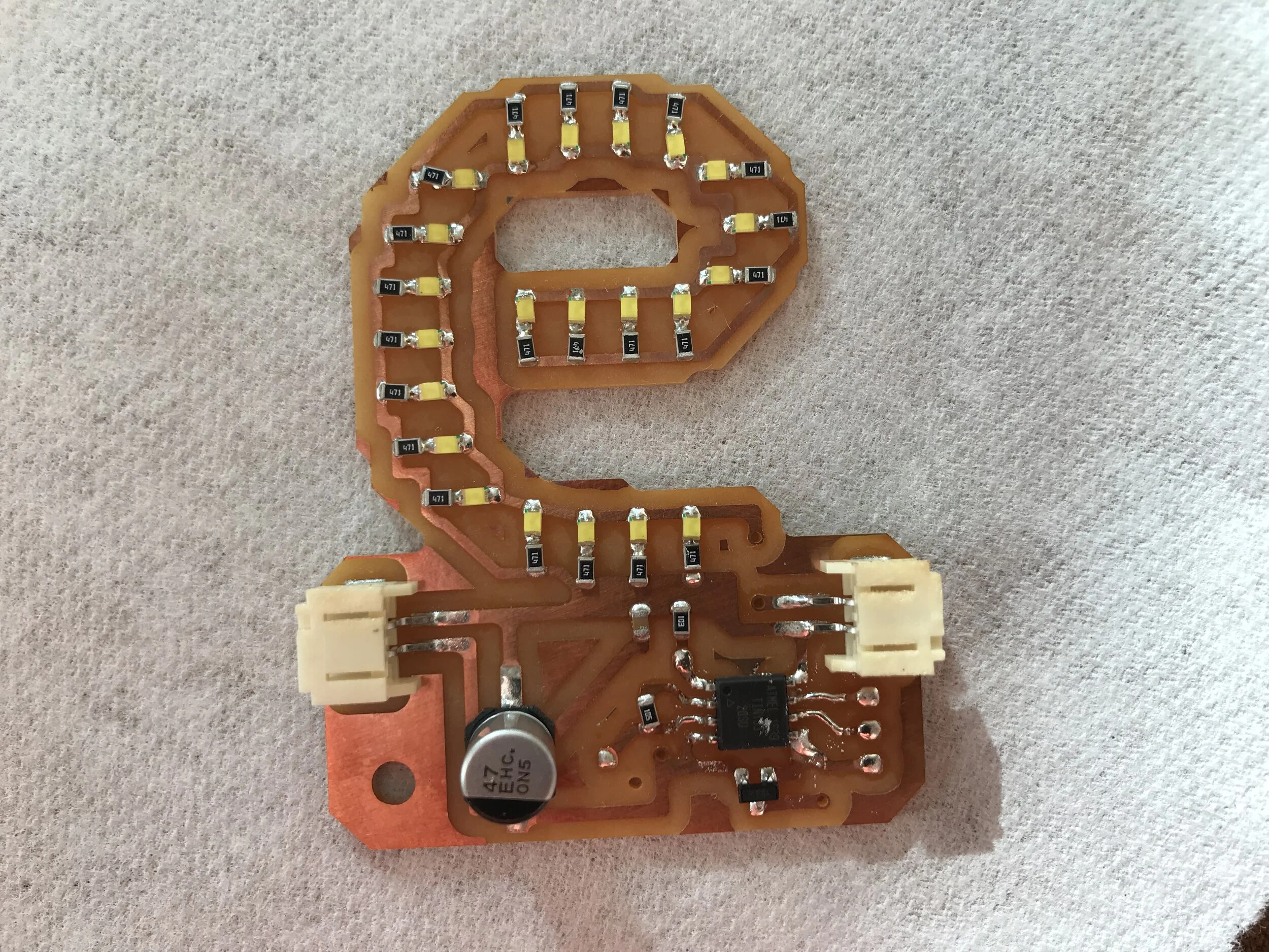
almost fully assembled board without the air-wires
programming the ATTiny
The programming was relatively straightforward as we had covered it in a previous class. Using an arduino UNO, the bootloader on the ATTiny was burned and a sketch with the capacitive sensor library was uploaded. At first, I had the lights turning on only when the coin was touched, but I figured since it is a marquee sign, it would make sense for it to be on consistently and flash faster when someone is pressing on the coin.
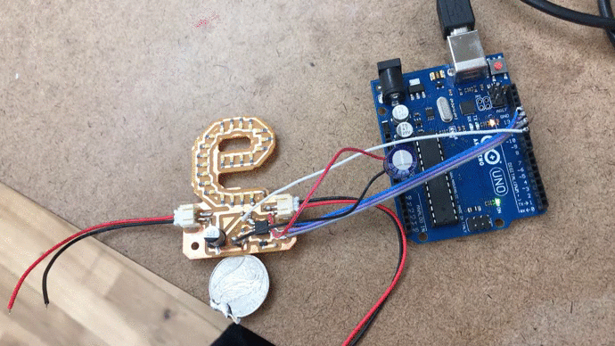
programming it with the arduino uno. the lights turn on only when there is capacitive touch.
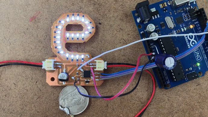
modified sketch that has lights constantly on and flashes when there is capcitive touch

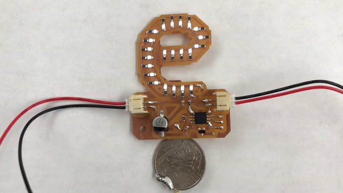
final piece with the data wires removed